Are you a road design engineer, architect, or simply passionate about simulating transportation projects? Mastering how to draw truck road angles in CAD is an indispensable skill. This article from Xe Tải Mỹ Đình (My Dinh Truck), a website specializing in trucks and related applications, will provide you with the most detailed and easy-to-follow instructions. We will simplify complex operations in CAD software, ensuring your drawings are not only accurate but also optimized for various types of trucks.
You may have searched for many tutorials on drawing angles in CAD, but the information is often general and lacks practical application for the trucking field. Our article below will offer an in-depth look, focusing on the needs of designing roads, parking lots, and facilities related to trucks, ensuring you can apply it directly to your work.
Why Drawing Truck Road Angles in CAD is Important?
Drawing angles in CAD is not just a basic technical operation, but also plays a crucial role in designing roads, truck parking lots, and other transportation infrastructure. Road angles directly affect the maneuverability, turning radius, and parking ability of various types of trucks with different sizes and weights. An accurate drawing down to each angle will help:
- Ensure traffic safety: Too sharp a curve can make it difficult for trucks to maneuver, leading to a risk of rollover or collision. Conversely, too wide a curve can waste space and is not economically optimal.
- Optimize space: In designing truck parking lots or cargo gathering areas, calculating and drawing accurate angles helps maximize space utilization, ensuring trucks can move and park conveniently.
- Save construction costs: Accurate CAD drawings help minimize errors during construction, avoiding the need for repairs or adjustments later, thereby saving costs and time.
- Comply with technical standards: Road and transportation infrastructure design standards clearly specify road angles, slopes, and other technical factors. Drawing accurate angles in CAD is the first step to ensure your drawings meet these standards.
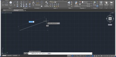 Illustration of the importance of road angles in truck road design
To draw truck road angles professionally and accurately, you need to master the tools and commands for drawing angles in CAD. The next section will guide you through 5 of the most common and effective methods for drawing angles, especially useful in road design and truck-related facilities.
5 Most Detailed Ways to Draw Truck Road Angles in CAD
Below are 5 methods for drawing angles in CAD that you can apply immediately to create professional and accurate truck road drawings:
1. Draw Truck Road Angles Using the Simple Line (L) Command
The Line command is the most basic tool in CAD, yet it is extremely effective for drawing truck road angles quickly and accurately. Follow these steps:
Step 1: Launch AutoCAD software and enter the command L (Line) into the command bar, then press Enter. Draw a horizontal line, representing a section of the truck road, by selecting a start point and an end point on the working screen.
 Step 1: Draw a horizontal line using the Line command in CAD to start drawing truck road angles
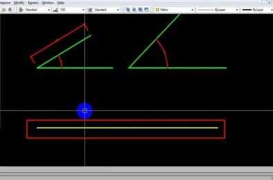
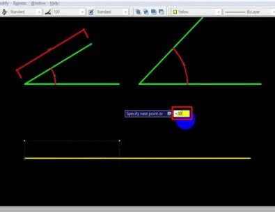
Step 2: Select the starting point of the line you just drew as the origin for creating the angle. Press the key combination Shift + < (less than sign) to activate the mode for entering a relative angle with respect to the horizontal.
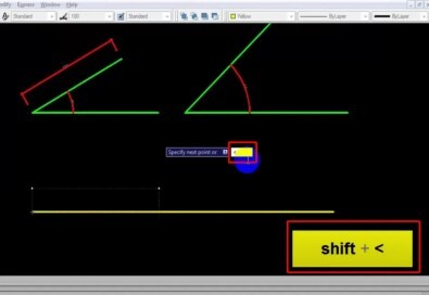 Step 2: Press Shift + < to enter a relative angle when drawing truck road angles in CAD
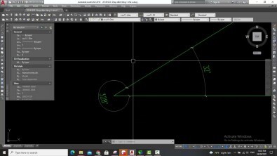
Step 3: Enter the desired angle value for the truck road. For example, if you want to draw a 30-degree angle, enter 30 and press Enter. This value will determine the inclination of the next line segment relative to the initial horizontal line.
 Step 3: Enter an angle value of 30 degrees to define the truck road angle in CAD
Step 4: Define the length of the angle line segment by moving the mouse or entering a specific length value. Press Enter to complete the Line command and finish the angle drawing process.
 Step 4: Define the endpoint and length of the angle line segment to complete drawing truck road angles in CAD
2. Combine Line Command and Relative Coordinates to Draw Truck Road Angles
Another way to draw truck road angles accurately is to combine the Line command with entering relative coordinates. This method is especially useful when you already know the length of the line segment and the angle to be created.
Step 1: Call the Line (L) command as in the method above and select the starting point for the angle line segment.
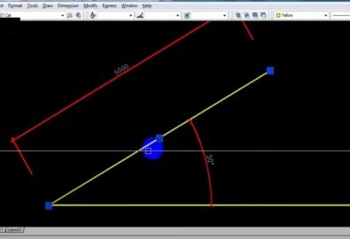
Step 2: Enter relative coordinates in the format @distance<angle. For example, to draw a line segment 70 units long and create a 30-degree angle relative to the horizontal, you enter @70<30 and press Enter. CAD will automatically draw a line segment with the length and angle exactly as you specified.
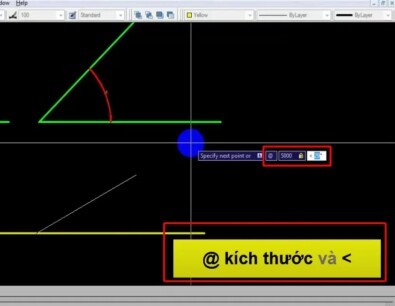 Step 2: Enter relative coordinates @70<30 to accurately draw truck road angles using CAD
Step 3: Press Enter to end the Line command after drawing the first angle line segment. Continue drawing other line segments to complete your truck road drawing.
3. Use the Xline (XL) Command to Draw Angular Axis Lines for Trucks
The Xline command (infinite line) is very useful when you need to create angular axis lines as reference lines for truck road design. Here’s how to do it:
Step 1: Enter the command Xline (XL) into the command bar and press Enter.
Step 2: Select the Angle option (or enter A and press Enter) to draw an Xline at an angle.
Step 3: Enter the desired angle value for the axis line. For example, enter 45 to create an Xline inclined at 45 degrees.
Step 4: Select a base point to place the Xline. The infinite line will be drawn through this base point and create an angle exactly as you specified. You can draw multiple Xlines with different angles to create a reference grid for truck road drawings.
 Steps to draw angular Xlines in CAD to create reference axis lines for truck roads
Step 5: Press Enter to end the Xline command.
4. Draw Truck Road Angles with Polar Tracking (F10) Support
Polar Tracking is a powerful angle drawing support feature in CAD. It helps you “snap” to preset angles, making it easy to draw truck roads at standard angles.
Step 1: Activate Polar Tracking by pressing the F10 key or clicking on the Polar Tracking icon in the status bar (usually located at the bottom right of the CAD screen). Make sure this icon is in the “on” state (usually blue or lit up).
Step 2: Enter the command DS (Drafting Settings) and press Enter to open the Drafting Settings dialog box. Select the Polar Tracking tab.
Step 3: In the Increment Angle section, select or enter the increment angle value that you want Polar Tracking to support. For example, if you choose 30, CAD will “snap” to angles 0, 30, 60, 90 degrees, etc. Select Relative to last segment to measure the angle relative to the line segment just drawn. Click OK to close the dialog box.
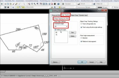 Setting Polar Tracking parameters in the Drafting Settings dialog box to accurately draw truck road angles
Step 4: Draw a line using the Line (L) command. When you move the mouse near the set angles (e.g., 30, 60 degrees), CAD will display a guide line and the Polar Tracking icon, indicating that you are drawing at the correct angle. Just click to confirm the point and draw the line segment at the desired angle.
5. Use the Rotate (RO) Command to Rotate Objects to Create Truck Road Angles
The Rotate (RO) command does not directly draw angles, but it is very useful for creating angles by rotating existing objects. For example, you can draw a straight road segment, then rotate it to create a curve for a truck road.
Step 1: Draw a straight road segment using the Line (L) command.
Step 2: Select the line segment you just drew, then enter the command RO (ROTATE) and press Enter.
Step 3: Select the base point for rotation. This point is usually one end of the line segment, or the intersection of lines.
Step 4: Enter C (Copy) and press Enter to create a copy of the original line segment before rotating. This helps you keep the original line segment and create a new one that forms an angle with it.
Step 5: Enter the desired rotation angle value. For example, enter 45 to rotate the line segment by 45 degrees. Press Enter to complete the Rotate command.
 Using the RO (Rotate) command to rotate road segments and create truck road angles in CAD
Step 6: Use commands like Trim (TR) or Fillet (F) to edit and remove excess parts, creating a complete and aesthetically pleasing truck road angle.
Important Notes When Drawing Truck Road Angles in CAD
- Units of measurement: Always check and set appropriate units of measurement before starting to draw. Ensure the units are meters or millimeters, depending on the drawing scale and design requirements.
- Accuracy: For transportation infrastructure and truck roads, accuracy is paramount. Use angle drawing commands and tools carefully, and thoroughly check angle and dimension parameters to ensure the drawing is error-free.
- Design standards: Refer to current road and transportation infrastructure design standards to ensure road angles and other technical factors meet regulatory requirements. Pay special attention to the turning radius and minimum turning angle for different types of trucks.
- Regular practice: To master the methods of drawing truck road angles in CAD, there is no better way than regular practice. Try drawing different types of angles, applying the above methods to specific truck road design exercises to improve your skills.
Conclusion
With the 5 detailed methods for drawing truck road angles that Xe Tải Mỹ Đình has just shared, we hope you have gained more useful knowledge and skills to serve your design work. Drawing angles accurately not only makes your drawings more professional, but also ensures safety and efficiency for truck-related transportation projects. We wish you success and the creation of impressive truck road drawings!
See more:
Overview of popular truck types in the Vietnamese market today